RF Cascade Workbook for Excel
RF & Electronics Symbols for Visio
RF & Electronics Symbols for Office
RF & Electronics Stencils for Visio
RF Workbench
T-Shirts, Mugs, Cups, Ball Caps, Mouse Pads
Espresso Engineering Workbook™
Smith Chart™ for Excel
|
|
About how to roughly measure LNA NF contour - RF Cafe Forums
|
| duplicity
|
 |
Post subject: About how to roughly measure LNA NF contour
Posted: Mon Apr 19, 2010 11:05 am
|
|
Joined: Mon Apr 19, 2010
10:51 am
Posts: 2 |
Hi RFCafe senior engineer, Good Day. I
have a serious issue about LNA NF measurement, and
really need your kindly support. What I want
to do is try to draw LNA NF and Gain circle by measurement,
and compare with simulation. Attach related file,
especially NF circle.
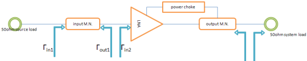
So, I set up a simple measurement, as shown
below: Here, I got several problem, 1. What
value of inductance I should use with power choke
inductor, refer to application circuit? 2. How
I define output M.N.? refer to application circuit?
3. If I do a simple output conjugate matching, should
I turn on LNA, if yes, is power choke a part of
matching network? 4. Here comes important problem,
4.1 What I can measure is total system(50ohm) NF,
and I want to determine LNA’s NF by equation.
4.2 For special case, that’s Гin1= Гout1= Гin2,
the FriiS equation is O.K. 4.3 But actual situation
is, Гin1≠ Гout1≠ Гin2, right? So how to modify FriiS
equation.
|
|
| |
|
 |
|
Itay |
|
Post subject: Re: About how to roughly measure LNA NF contour
Posted: Tue Apr 20, 2010 3:19 pm
|
|
Joined: Tue Apr 20, 2010
2:35 pm
Posts: 1 |
Hello duplicity, I will try to answer on
some of your questions:
Quote:
1. What value of inductance I should use with
power choke inductor, refer to application circuit?
The inductor value should give you a reactance
of several hundreds ohms (at least 300 ohms) in
your lowest frequency of operation. remember that
as the frequency increases, XL increases as well.
In addition, you should choose the inductor
such that its SRF (Self-Resonance Frequency) would
be at least twice higher than your maximal frequency
of operation in order to avoid a capacitive reactance.
Quote:
How I define output M.N.? refer to application
circuit?
Usually for LNA, you define the output matching
network as one for conjugate match. This is because
the input matching for noise figure degrades the
return loss at the input and reduces the overall
gain (mismatch), and as a result you loose power.
Quote:
If I do a simple output conjugate matching,
should I turn on LNA, if yes, is power choke
a part of matching network?
You should design the output matching only
after your input mtaching network is fully designed
and connected to the LNA, because the input matching
network will affect your S22. The reason for that
is that the amplifier is not unilaterlal, i.e. there
is a certain feedback from the output to the input
S12. The choke (power inductor as you named
it) if properly chosen, should slightly influcnece
on the output mathcing network. Actually, it isolates
between the supply voltage to the matching network.
Usually from RF signal point of view, it only slightly
increases the gain. So your output matching
newtok should be designed to the conjugate of the
modified S22 (With the influence of the input matching
network). You should turn on the LNA, in
order to measure the output power. ____________
In general, when designing matching networks,
pay attention to the stability of the amplifier.
It is very important to check that your required
reflection coefficients are located within the stable
region. You can perform stability simulation
or calculate K (Rollet's Factor). For unconditional
stability K>1
|
|
| |
|
|
|
|
duplicity |
|
Post subject: Re: About how to roughly measure LNA NF contour
Posted: Thu Apr 22, 2010 10:56 am
|
|
Joined: Mon Apr 19, 2010
10:51 am
Posts: 2 |
Quote:
In addition, you should choose the inductor
such that its SRF (Self-Resonance Frequency)
would be at least twice higher than your maximal
frequency of operation in order to avoid a capacitive
reactance.
I will kind in my mind, thanks for your lesson
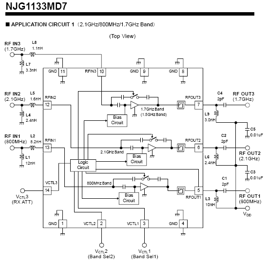
learn. But actually, the reference design is
around 3nH(LQP03TN3N0B04), whose SRF is over 6GHz,
and impedance is only 38.46ohm at 1990MHz.
Quote:
You should design the output matching only after
your input mtaching network is fully designed
and connected to the LNA, because the input
matching network will affect your S22. The reason
for that is that the amplifier is not unilaterlal,
i.e. there is a certain feedback from the output
to the input S12.
But how about isolation?! The input M.N. should
not influence S22 load. How i tine the S22 M.N.
is tep by: 1. S11 should be ready first. 2.
tune choke to get higher gain. 3. tune second
componet for conjugate matching.
Quote:
You can perform stability simulation or calculate
K (Rollet's Factor). For unconditional stability
K>1
Thank you for your kindly reply.
|
|
| |
|
|
|
|
IR |
|
Post subject: Re: About how to roughly measure LNA NF contour
Posted: Thu Apr 22, 2010 2:57 pm
|
|
| |
| Site Admin |
 |
Joined: Mon Jun 27, 2005
2:02 pm
Posts: 406
Location: Germany
|
Quote:
But actually, the reference design is around
3nH(LQP03TN3N0B04), whose SRF is over 6GHz,
and impedance is only 38.46ohm at 1990MHz.
3nH to my opinion is too low. The SRF is
OK. From my experience: I designed an amplifier
for 2.7GHz and I chose a choke of 8.2nH.
Quote:
But how about isolation?! The input M.N. should
not influence S22 load.
How i tine the S22
M.N. is tep by:
1. S11 should be ready first.
2. tune choke to get higher gain.
3. tune
second componet for conjugate matching.
As I mentioned, the isolation is not infinite,
i.e. the amplifier is not unilateral (ideal).
There is S12 which has a low but not negligible
value. I would perform the following steps
- simulation only. 1) Design the input matching
network for the required gain and NF (You have to
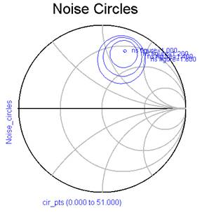
find the intersection point of the desired Noise
and gain circles) with the output matched to 50-ohm.
2) After that, plot S22 of the amplifier (With the
input matching network). 3) Design the output
matching network for congugate match. Also add the
choke value and see how it affects the output matching
and gain. 4) Tune both the input and output
networks for optimal performance.
_________________
Best regards,
-
IR
|
|
Posted 11/12/2012
|
|

Copyright: 1996 - 2024
Webmaster:
Kirt
Blattenberger,
BSEE - KB3UON
RF Cafe began life in 1996 as "RF Tools" in an AOL screen name web space totaling
2 MB. Its primary purpose was to provide me with ready access to commonly needed
formulas and reference material while performing my work as an RF system and circuit
design engineer. The World Wide Web (Internet) was largely an unknown entity at
the time and bandwidth was a scarce commodity. Dial-up modems blazed along at 14.4 kbps
while tying up your telephone line, and a nice lady's voice announced "You've Got
Mail" when a new message arrived...
|
All trademarks, copyrights, patents, and other rights of ownership to images
and text used on the RF Cafe website are hereby acknowledged.
|
|
All trademarks, copyrights, patents, and other rights of ownership to images
and text used on the RF Cafe website are hereby acknowledged.
My Hobby Website: AirplanesAndRockets.com
My Daughter's Website: EquineKingdom
|
|
|
|


