RF Cascade Workbook for Excel
RF & Electronics Symbols for Visio
RF & Electronics Symbols for Office
RF & Electronics Stencils for Visio
RF Workbench
T-Shirts, Mugs, Cups, Ball Caps, Mouse Pads
Espresso Engineering Workbook™
Smith Chart™ for Excel
|
|
Question on test scheme design for 4-port microstrip circuit - RF
Cafe Forums
|
| sageme
|
|
Post subject: Question on test scheme design for 4-port microstrip
circuit
Posted: Thu Sep 24, 2009 2:39 pm
|
|
Joined: Wed Jul 09, 2008
11:51 am
Posts: 4
Location: Chicago
|
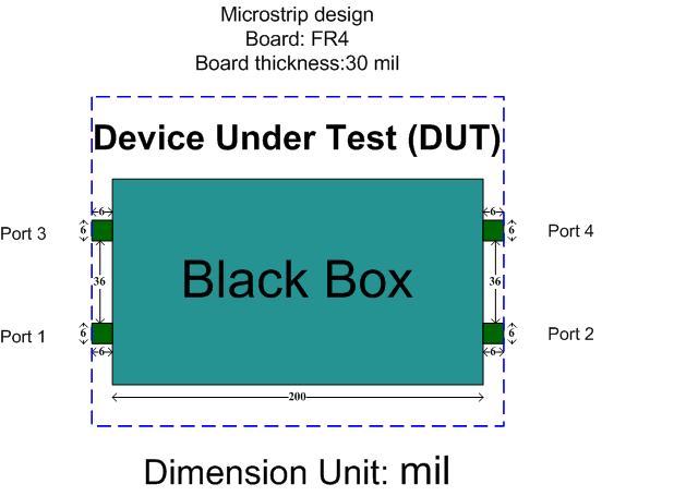
Dear all, I designed a small four-port microstrip
circuit (device under test), and obtained the simulation
results. Since this 4-port microstrip circuit is
very small, it does not have enough space for SMA
connector mounting. Now I want (but I have no idea)
to design a proper test scheme for purpose of the
SMA-connector measurement of S parameters of this
tiny four-port DUT by using four-port vector network
analyzer. I really appreciate whatever help you
could offer me on the test scheme design.
Thanks a lot. Sincerely yours, Kevin
_________________
Pursuing perfectness pushes
us to progress
|
|
| |
|
 |
|
Jessica |
|
Post subject: Re: Question on test scheme design for 4-port microstrip
circuit
Posted: Thu Sep 24, 2009 3:46 pm
|
|
| |
| Captain |
 |
Joined: Thu Oct 12, 2006
7:50 am
Posts: 6 |
Hi Sageme, If you only have a couple DUTs
to measure, then you can probably solder a short
section of small semi-rigid coax to the board that
has an SMA on the other end. I've had great success
with that up into the 6 GHz region (could probably
go higher, butI've never needed to). For
measuring a large number of DUTs, a fixture will
be necessary. I've never used one myself, but I
see that a company called Gigalane has a productio
quality fixture for measuring your type of PCB.
http://www.gigalane.com/index.html?mode=02_01_01_01&pduid=93
_________________
Thanks,
Jess
|
|
| |
|
|
|
|
sageme |
|
Post subject: Re: Question on test scheme design for 4-port microstrip
circuit
Posted: Mon Sep 28, 2009 12:13 pm
|
|
Joined: Wed Jul 09, 2008
11:51 am
Posts: 4
Location: Chicago
|
Dear Jessica, Thanks a lot for the information
your provided. Actually, I only have a couple
of DUTs to measure. I think it may be very difficult
to solder a short section of small semi-rigid coax
to the board for measurement, since our DUTs are
so miniature that it may not have enough space for
soldering. The distance between two adjacent ports
is about 36mil=0.9mm on the same side (as indicated
in the picture above), and the distance between
adjacent port is about 164mil=4.2mm on two adjacent
sides, which is the same as the DUT's length.
For the test fixture in your reply, it might
be not proper for our measurement for the same reason
that our DUT is too miniature. I checked the specifications
of this test fixture. It requires that minimum length
of DUT is 9mm and minimum width of DUT is 2.5mm.
What do you think of this? Or could you please
offer some suggestions? Thank you so much!
Sincerely, Kevin
Jessica wrote:
Hi Sageme, If you only have a couple
DUTs to measure, then you can probably solder
a short section of small semi-rigid coax to
the board that has an SMA on the other end.
I've had great success with that up into the
6 GHz region (could probably go higher, butI've
never needed to). For measuring a large
number of DUTs, a fixture will be necessary.
I've never used one myself, but I see that a
company called Gigalane has a productio quality
fixture for measuring your type of PCB.
http://www.gigalane.com/index.html?mode=02_01_01_01&pduid=93
_________________
Pursuing perfectness pushes
us to progress
|
|
Posted 11/12/2012
|
|

Copyright: 1996 - 2024
Webmaster:
Kirt
Blattenberger,
BSEE - KB3UON
RF Cafe began life in 1996 as "RF Tools" in an AOL screen name web space totaling
2 MB. Its primary purpose was to provide me with ready access to commonly needed
formulas and reference material while performing my work as an RF system and circuit
design engineer. The World Wide Web (Internet) was largely an unknown entity at
the time and bandwidth was a scarce commodity. Dial-up modems blazed along at 14.4 kbps
while tying up your telephone line, and a nice lady's voice announced "You've Got
Mail" when a new message arrived...
|
All trademarks, copyrights, patents, and other rights of ownership to images
and text used on the RF Cafe website are hereby acknowledged.
|
|
All trademarks, copyrights, patents, and other rights of ownership to images
and text used on the RF Cafe website are hereby acknowledged.
My Hobby Website: AirplanesAndRockets.com
My Daughter's Website: EquineKingdom
|
|
|
|
